Each Basic Hydraulics training system features standard industrial grade components. This attention to quality gives students experience they would normally only get on-the-job by helping them recognize industrial components and how to troubleshoot them more effectively. Components included with Basic Hydraulics are pre-mounted on circuit panels with silk-screened labels next to each, which facilitates ease of use and identification.
Take a behind-the-scenes look at the Matrix Fundamental Fluids training system as it is unpacked and assembled. This video showcases the thoughtful design and modular construction of the workstation, giving educators and students a closer look at the engineering that goes into creating a versatile fluid mechanics training solution.
Designed for mechanical, civil, and multidisciplinary engineering programs, the Matrix Fluid Mechanics Rig features a robust workstation with interchangeable experiment modules that can be assembled quickly without specialized tools. The modular design allows institutions to efficiently support multiple laboratory activities while minimizing setup time between experiments.
Whether you're evaluating equipment for a new laboratory or simply interested in how the system is built, this video provides a unique look at the quality, attention to detail, and practical design philosophy behind Matrix engineering education solutions.
Mechanisms Fundamentals is the newest addition to the Matrix mechanical engineering range, providing students with a practical introduction to the principles that power countless machines and mechanical systems.
Using the included storable work panel, learners quickly assemble a variety of experiments that demonstrate the operation and performance of gears, cams, crank mechanisms, and mechanical drive systems. By building and testing each mechanism, students gain a deeper understanding of force transmission, motion, mechanical advantage, efficiency, displacement, and gear ratios while reinforcing classroom theory through hands-on investigation.
A comprehensive 10-hour workbook, available free through the Matrix Learning Center, guides students through each experiment with structured activities, theory, and analysis. The system is ideal for mechanical engineering, manufacturing technology, engineering technology, and technical education programs seeking engaging laboratory experiences.
Learning Objectives
Mechanisms Fundamentals includes a comprehensive series of practical experiments that introduce students to the operation and analysis of common mechanical systems. Through hands-on investigation, learners explore how gears, cams, crank mechanisms, and drive systems transmit motion and force while developing a deeper understanding of mechanical advantage, efficiency, gear ratios, and displacement.
Investigate mechanical advantage (MA), efficiency, and gear ratios using a variety of gear systems.
- Simple Gear
- Compound Gear
- Rack & Pinion
- Bevel Gear
- Worm Gear
- Screw Jack
Study displacement characteristics produced by different cam profiles.
- Tangent Cam
- Snail Cam
- Eccentric Cam
Analyze force transmission and displacement using crank mechanisms.
- Force Analysis
- Displacement Analysis
Compare mechanical advantage, efficiency, and power transmission across multiple drive systems.
- Universal Joint
- Belt Transmission
- Chain Transmission
Watch the video to see how Mechanisms Fundamentals helps students visualize engineering concepts, quickly assemble experiments, and build practical skills in mechanical systems.
The Matrix Wind Tunnel provides a versatile platform for investigating the fundamental principles of aerodynamics through hands-on experimentation. Designed for engineering education, the system enables students to visualize airflow and collect real experimental data while reinforcing the theory taught in the classroom.
In this video, we showcase the range of experiments available with the Matrix Wind Tunnel and demonstrate how quickly students can configure the equipment for different investigations. From measuring lift and drag to analyzing pressure distribution and airflow characteristics, each experiment helps learners develop a deeper understanding of aerodynamic behavior and experimental analysis.
Watch the video to explore the available experiments and see how the Matrix Wind Tunnel supports engaging, practical learning in mechanical and aerospace engineering programs.
This video demonstrates the Matrix Deflection of Beams experiment operating in manual mode, allowing students to perform hands-on structural engineering investigations while following the included curriculum workbook. As the second video in the Structures series, it highlights how the same equipment can be used without data acquisition, helping learners develop practical measurement, observation, and analytical skills.
Students assemble the apparatus, install different beam materials and support configurations, and measure beam deflection using a precision dial gauge. By applying incremental loads and recording measurements, they investigate how support conditions and material properties influence structural behavior. The resulting data can then be plotted and analyzed to compare theoretical calculations with experimental results, reinforcing key concepts in mechanics of materials and structural engineering.
What You'll Learn
- How to set up the Deflection of Beams experiment in manual mode
- The differences between fixed supports and cantilever support arrangements
- How beam material and support configuration affect deflection
- Using precision measuring equipment to record beam displacement
- Applying incremental loads and collecting experimental data
- Converting measurements into SI units for engineering calculations
- Plotting deflection versus load graphs and calculating gradients
- Comparing experimental results with structural engineering theory
Why Manual Mode Matters
Manual operation encourages students to take ownership of the experimental process by setting up the apparatus, collecting measurements, recording observations, and interpreting results independently. This approach strengthens practical laboratory skills while reinforcing the engineering principles behind beam deflection, structural supports, and material behavior.
This video demonstrates the Matrix Bending Moments experiment operating in manual mode, giving students a practical understanding of how loads create bending moments within a beam. By following the included curriculum workbook, learners collect real experimental data and compare measured values with theoretical calculations, reinforcing key principles of structural engineering and mechanics.
During the experiment, students move a fixed load to multiple positions along the beam while the integrated load cell measures the resulting forces. The measured data is recorded, analyzed, and used to calculate support reactions and bending moments before being plotted on a graph for comparison with theoretical predictions. This hands-on investigation helps students visualize how load position influences internal beam forces and structural behavior.
What You'll Learn
- How to set up the Bending Moments experiment in manual mode
- How load position affects bending moments within a beam
- Using an integrated load cell to measure reaction forces
- Recording and analyzing experimental data
- Calculating reaction forces at beam supports
- Comparing measured and theoretical bending moment values
- Plotting graphs to analyze structural behavior
- Developing practical skills in structural engineering experimentation
Why Study Bending Moments?
Understanding bending moments is fundamental to structural and civil engineering. This experiment allows students to investigate how beams respond to different loading conditions, validate engineering theory through experimentation, and build confidence interpreting structural analysis using real-world measurements.
This video demonstrates the Matrix Shear Force experiment using data acquisition mode, allowing students to investigate how applied loads create shear forces within a beam. Following the guided curriculum workbook, learners collect accurate experimental data while developing a practical understanding of structural behavior and beam analysis.
During the experiment, students apply incremental loads to the beam while an integrated load cell continuously measures the resulting shear force. The measurements are automatically recorded using the Matrix data acquisition software and exported for analysis. Students then use the collected data to create graphs, compare experimental results with engineering theory, and develop a deeper understanding of shear force diagrams and structural mechanics.
What You'll Learn
- How to perform a shear force experiment using data acquisition
- How integrated load cells measure shear force within a beam
- Investigating the effects of changing point loads and load positions
- Recording experimental data using Matrix data acquisition software
- Applying incremental loading to analyze structural response
- Exporting data for graphing and post-experiment analysis
- Interpreting shear force graphs and engineering results
- Reinforcing structural engineering concepts through hands-on investigation
Why Study Shear Forces?
Shear forces play a critical role in the design and analysis of beams and structural members. This experiment allows students to collect real measurement data, visualize how shear forces change under different loading conditions, and connect theoretical calculations with practical engineering observations.
This video demonstrates the Matrix Torsion of Rods experiment in manual mode, where students investigate how different materials respond to applied torque. Following the included curriculum workbook, learners compare the torsional characteristics of brass, aluminum, and steel rods while collecting experimental data for analysis.
During the investigation, students install each rod, measure its dimensions, and gradually increase the angle of twist while recording the torque required at each increment. The experiment is repeated for each material, allowing students to compare torque-versus-angle relationships and better understand material properties, torsional stiffness, and structural behavior through practical experimentation.
What You'll Learn
- How to set up the Torsion of Rods experiment in manual mode
- Comparing the torsional behavior of brass, aluminum, and steel rods
- Measuring torque and angle of twist using integrated LCD displays
- Recording experimental measurements for multiple materials
- Investigating the relationship between torque and angular displacement
- Repeating experiments to compare material properties
- Plotting torque versus angle graphs for analysis
- Reinforcing engineering concepts through hands-on laboratory investigations
Why Study Torsion?
Torsional loading is an important consideration in the design of shafts, drive systems, fasteners, and structural components. This experiment gives students practical experience measuring the effects of torque on different materials, helping them connect engineering theory with real-world mechanical behavior and material performance.
This video demonstrates the Matrix Bending Stress experiment using data acquisition mode, allowing students to investigate how bending loads create stress within a beam. Using the included curriculum workbook, learners configure strain gauges, collect real-time measurement data, and perform engineering analysis to validate theoretical calculations.
Students begin by configuring a quarter-bridge Wheatstone bridge circuit using strain gauges and precision resistors before applying incremental loads to the beam. As each load is added, measurements are captured through the integrated data acquisition system and exported for analysis. The resulting data allows students to calculate bending stress, compare theoretical and experimental results, and gain practical experience with strain measurement techniques used throughout structural and mechanical engineering.
What You'll Learn
- How to configure a quarter-bridge Wheatstone bridge using strain gauges
- Setting up the Bending Stress experiment using data acquisition
- Applying incremental loads to investigate bending stress
- Collecting real-time strain measurements using integrated sensors
- Measuring beam dimensions for engineering calculations
- Exporting experimental data for post-laboratory analysis
- Comparing theoretical bending stress calculations with measured results
- Developing practical skills in experimental stress analysis
Why Study Bending Stress?
Measuring bending stress is fundamental to understanding how structural components perform under load. This experiment introduces students to strain gauge technology, Wheatstone bridge circuits, and modern data acquisition methods while reinforcing core concepts in mechanics of materials, structural analysis, and engineering design.
This video provides an overview of the Matrix Fundamental Mechanics Materials Kit, demonstrating how students perform practical experiments to investigate the mechanical properties of engineering materials. Designed for classroom and laboratory environments, the kit allows learners to build experiments using the portable work panel while following the included curriculum workbook.
The featured experiment investigates how an aluminum beam deflects under increasing loads. Students measure the beam's dimensions, apply incremental weights, and use a precision dial gauge to record deflection. The collected data is then plotted on a graph, helping students understand the relationship between load and beam deflection while reinforcing important concepts in material science and mechanics.
What You'll Learn
- How to perform beam deflection experiments using the Materials Kit
- Measuring beam dimensions for engineering calculations
- Recording beam deflection with a precision dial gauge
- Applying incremental loads and collecting experimental data
- Plotting deflection versus load graphs for analysis
- Understanding stress, strain, and elastic behavior
- Exploring Young's modulus and other material properties
- Developing practical laboratory and engineering analysis skills
Topics Covered by the Materials Kit
The Fundamental Mechanics Materials Kit supports a wide range of experiments covering beam deflection, stress and strain, torsion, elastic constants, Young's modulus, and other core principles of mechanics of materials. The included curriculum provides approximately 10 hours of guided laboratory activities that combine theory with practical investigation, making it ideal for engineering, technology, and STEM education programs.
The Matrix Fundamental Mechanics Dynamics Kit introduces students to the core principles of dynamics through a series of engaging, hands-on laboratory experiments. Designed for engineering, physics, and STEM education, the kit uses a portable work panel and a guided curriculum to help learners investigate the behavior of moving systems and connect theoretical concepts to practical applications.
In this video, students complete a flywheel experiment from the included curriculum to measure the effects of applied loads on rotational motion. By recording experimental data, calculating torque and angular acceleration, and analyzing graphical results, learners gain valuable insight into rotational dynamics while developing essential laboratory and engineering analysis skills.
Key Engineering Concepts
- How to perform flywheel experiments using the Dynamics Kit
- Investigating the relationship between torque and angular acceleration
- Measuring rotational motion using experimental techniques
- Recording, averaging, and analyzing laboratory data
- Plotting and interpreting engineering graphs
- Exploring pulleys, mechanisms, and energy conservation
- Investigating static and sliding friction
- Developing practical laboratory and engineering problem-solving skills
Topics Covered by the Dynamics Kit
The Fundamental Mechanics Dynamics Kit supports approximately 10 hours of guided laboratory activities covering flywheels, pulleys, static and sliding friction, mechanical mechanisms, and energy conservation. Each experiment encourages students to collect real experimental data, compare observations with engineering theory, and build a strong foundation in dynamics and mechanical engineering principles.
Pages
-
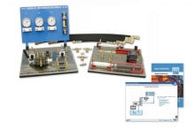 Item Number:BH-85
 -
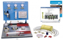 Item Number:85-BPAmatrol’s Basic Pneumatics training system (85-BP) introduces pneumatic principles through a combination of Amatrol’s top-flight multimedia curriculum with hands-on industrial pneumatic skill-building. Topics covered in this learning system include single-acting cylinder circuits, pressure vs. cylinder force, and flow control valves, while the panels can be used to practice skills such as connecting and operating a needle valve to control actuator speed.
 -
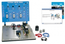 Item Number:85-EHThe Electro-Hydraulics training system includes an electrical control panel with relay control components and an electrical valve module with solenoid-operated hydraulic directional control valves and electrical/electronic sensors. These components will be used to study a variety of topics including electrical control systems, basic control devices, power devices, control relays, sequencing control, timer control, pressure control applications, and circuit applications.
 -
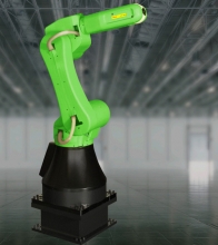 Item Number:CR-35iAFANUC’s new CR-35iA is the world’s first collaborative robot with a payload capacity of up to 35 kg. Fenceless, it opens a whole new world of possibilities. Working safely side by side with human operators, it is space as well as cost saving. And because inside it’s like any other FANUC robot, it operates like all FANUC robots. Certified to meet the requirements of ISO 10218-1:2011 and RIA/ANSI R15.06-2012, FANUC’s CR-35iA collaborative robot can work in a variety of applications alongside human workers including: machine tending, handling heavy payloads that require lift assist devices or custom equipment, higher payload mechanical assembly, palletizing or packing, and tote or carton handling.
 -
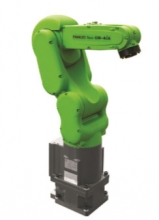 Item Number:CR-4iACR-4iA is a small collaborative robot with 4 kg payload
 -
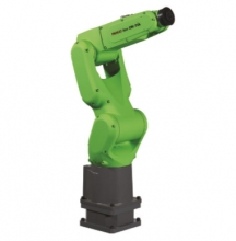 Item Number:CR-7iAThe FANUC CR-7iA is FANUC's newest collaborative robot resembles the LR Mate family. Painted green to show it's ability to work beside humans, you can expect the same reliability as FANUC's yellow robots. The CR-7iA is ideal for small part sorting and assembly, inspection, machine tending, and part delivery. It has a 7 kg payload, 717 mm reach, and is equipped with iRVision and Force Sensing. There are a variety of mounting options such as floor, wall, and ceiling.
 -
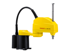 FANUC’s new SCARA robots are ideal for high-speed, precision applications such as assembly, pick and place, testing/inspection and packaging processes.
 -
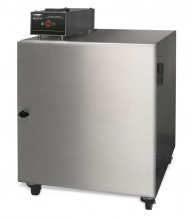
In the rare event that a burning ember or spark is drawn into the fume extraction unit, there is the possibility that debris in the filters could ignite. Although any resultant fire would typically be retained within the fume extraction unit, this would cause significant damage and in extreme circumstances, the risk may extend beyond the extraction unit. For processes where such risks have been identified, additional protection in the form of an in-line firebox is an additional precaution.
-
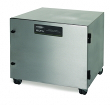
The BOFA inline pre-filter 1000 has been designed specifically for applications that generate high amounts of dust or particulate.
This inline filter unit is positioned alongside the main BOFA fume filtration system to increase the overall filter capacity and extend the life of the main filters. The DeepPleat DUO pre-filter incorporates a massive drop-out chamber within the filter, having a volume area of 15ltrs. Above the drop-out chamber but still within the housing there is a sealed 200mm deep pleat layer of F8 media giving a surface area in excess of 30 sq meters.
-
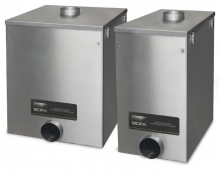 The BOFA inline prefilters have been designed specifically for applications that generate high amounts of dust or particulate.